What is a Load Bank?
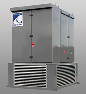
A Load Bank is a device which develops an electrical load, applies the load to an electrical power source and converts or dissipates the resultant power output of the source. A Load Bank is intended to accurately mimic the operational or “real” load which a power source will see in actual application.
However, unlike the “real” load, which is likely to be dispersed, unpredictable and random in value, a Load Bank provides a contained, organized and fully controllable load. Consequently, a Load Bank can be further defined as a self-contained, unitized, systematic device which includes both load elements with control and accessory devices required for operation.
Where the “real” load is served by the power source and uses the energy output of the source for some productive purpose, the Load Bank serves the power source, using its energy output to test, support or protect the power source.
Applications
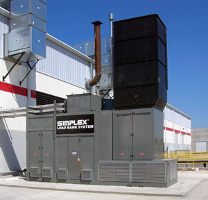
Load Banks are used with Engine Generators, Battery Systems, UPS Systems, Inverters, Ground Power Units, Auxiliary Power Units, Aircraft Power Generators, Wind Generators, and Hydro Generators.
Load Banks can be used for several purposes, including:
Manufacturing Testing
Generator Test Cells
Manufacturers of standby power generators commonly use load banks to test and tune newly assembled units.
When the generator has been set up in a test cell within the factory, a test engineer uses the load bank to apply a discrete, selectable electrical load to the generator and measure the response stability and endurance. During this process, the test engineer calibrates and adjusts the generator performance to ensure it meets the intended product specifications and tolerances.
Engine Test Cells
Manufacturers of small gas engines also use load banks to test newly manufactured engines under various mechanical loads. This is accomplished by connecting the engine to the load bank via a device called a dynamometer. Again, engine performance is monitored and, if necessary, adjustments are made to ensure the product performs within intended specifications.
Field Testing & Exercise
Generators installed in the field must be periodically tested and exercised to ensure that it will operate as intended when a power outage actually occurs. Service groups use load banks to apply a load that mimics the load of the facility the generator is protecting. Any problems with the generator can then be identified and rectified in a non-critical environment.
Simplex Load Banks can be used to satisfy the requirements of the National Fire Protection Association (NFPA) for emergency stand-by power systems. These requirements concern acceptance testing and periodic on-site testing and maintenance of emergency and stand-by power systems. The essence of the requirements is that emergency and stand-by power systems are to be tested under load.
Elimination of ‘Wet Stacking’
Load banks may be installed in a diesel powered generator set to apply the additional load required to ensure the engine fully consumes the fuel in the combustion process. If a diesel engine is not operated under adequate load, unconsumed fuel will collect in the engine’s exhaust stack and form an oily coating.
Demonstration
Load banks are often used as tool for demonstrating to buyers and users of a new generator set that the unit meets the performance specifications outlined in the purchase contract.
Load Bank Types
Resistive
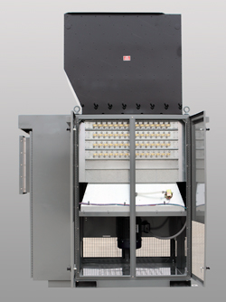
Load Banks are used with Engine Generators, Battery Systems, UPS Systems, Inverters, Ground Power Units, Auxiliary Power Units, Aircraft Power Generators, Wind Generators, and Hydro Generators.
A Resistive load bank, the most common type, proves equivalent loading of both generator and prime mover. That is, for each kilowatt (or horsepower) of load applied to the generator by the load bank, an equal amount of load is applied to the prime mover by the generator.
A resistive load bank, therefore, removes energy from the complete system: load bank from generator—generator from prime mover—prime mover from fuel. Additional energy is removed as a consequence of resistive load bank operation: waste heat from coolant, exhaust and generator losses and energy consumed by accessory devices. A resistive Load Bank impacts upon all aspects of a generating system.
The “load” of a resistive load bank is created by the conversion of electrical energy to heat by power resistors. This heat must be dissipated from the Load Bank, either by air or by water, by forced means or convection.
In a testing system, a resistive load simulates real-life resistive loads, such as lighting and heating loads as well as the resistive or unity power factor component of magnetic (motors, transformers) loads.
Reactive
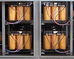
A “reactive” load includes inductive (lagging power factor) and/or capacitive (leading power factor) loads.
Inductive
Inductive loads, the more common type, consist of iron-core reactive elements which, when used in conjunction with a resistive load bank, create a lagging power factor load. Typically, the inductive load will be rated at a numeric value 75% that of the corresponding resistive load such the when applied together, a resultant 0.8 power factor load is provided. That is to say, for each 100KW of resistive load, 75KVAR of inductive load is provided.
Other ratios are possible to obtain other power factor ratings. Inductive loads are used to simulate real-life mixed commercial loads consisting of lighting, heating, motors, transformers, etc.
With a resistive/inductive load bank, full power system testing is possible given the impact of reactive currents on generator/voltage regulator performance as well as effects on conductors and switchgear.
Capacitive
A capacitive load bank is similar to a reactive load bank in rating and purpose, except that leading power factor loads are created. These loads simulate certain electronic or non-linear loads typical of telecommunications, computer or UPS industries.
Load Bank Components
Load Elements
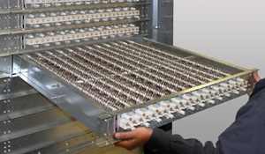
Simplex Load Banks utilize the UL Recognized, “Powr-Web” load element. The “Powr-Web” is an advanced design, air-cooled power resistor specifically designed for use in load bank systems.
The “Powr-Web” is conservatively operated at half the maximum temperature rating of the alloy and features a short-circuit-safe design based on continuous mechanical support of the resistor by high temperature, ceramic clad stainless steel rods. The “Power Webs” are assembled into discrete trays which are assembled in a vertical “stack.” Each tray in the “stack” is independently serviceable without disturbing adjacent trays.
Specifications Alloy: FeCrAl Max. continuous temp. rating: 1920°F Maximum operating temperature as applied in Load Bank: 1080° F Cool down time from operating to ambient temperature: 10 seconds.
Enclosures
Load banks are made in several form factors, depending upon the application and the environment in which it will be installed.
Portable
When a load bank needs to be moved frequently, it can be built to accommodate portability. A load bank enclosure can incorporate forklift channels, lifting eyes or casters to facilitate transportability.
Additionally, service groups that provide mobile load bank testing often utilize load banks mounted on trailers or service vehicles.
Stationary
Load banks are typically permanently mounted on concrete pads next to a generator set being served. If the installation is indoors, the load bank can be enclosed in a NEMA-1 cabinet. For out of doors installation, a NEMA-3R enclosure is typically used.
Load banks can also be directly mounted to the radiator of the generator set. Duct mounted installations are cooled by the radiator airflow, thus allowing for a tight fit between the load bank and generator set. The primary benefit of this approach is to conserve space.
Controls & Instrumentation
Load banks can be controlled via local, remote or automatic control panels.
Local - Control panel self-contained in Load Bank.
Remote - Control panel placed in a location away from the physical load bank.
Automatic - Wide variety of auto control available including auto on-off, auto load regulation, KW or reverse power response, computer control.
Controls can also be mechanical or digital. Digital controls require the use of a Programmable Logic Controller (PLC) to translate digital commands into mechanical switching.
Mechanical – Physical toggle switches, indicator lights and alarms.
Touch Screen – LCD display with touch activated controls. Touch screens can be programmed and modified to meet a customer’s exact requirements and the specific capabilities of the unit it is installed within.
Software – Simplex’ AutoTest software runs on a personal computer and can be used to remotely control and monitor load banks with precise control.
Load Connectors
Power sources to be tested can be connected to the load bank in several ways.
Cable Set - Connection cable included with Load Bank. Typical of portable units. Cable sets can be connected to the load bank with Cam-Lok plugs, lug style connectors or via bare braded wire ends.
Terminal Block - Power terminals for connection of building cables. Typical of stationary and duct mounted units.
Plugs - To match commercial wiring devices, aircraft plugs, MIL-SPEC plugs, cam-lock connections.
System Protections
It is advisable to protect the load bank from the potential hazards inherent in high voltage applications. Simplex load banks employ protections specifically for this purpose.
Short Circuit Protection - Load element branch circuit fuse or circuit breaker protection
System Protection - Protected against running failures (fan fail, over temperature, over voltage, etc.).
Cooling Systems
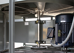
Natural Convection Air Systems may be used up to a 20 KW maximum.
Load elements are cooled via Natural Convection Air, Integral Fan Forced Air, Radiator Airflow, or Water Flow.
Integral Fan Forced Air Systems for resistive load elements consist of an aluminum fan blade (shrouded for high efficiency) directly driven or belt driven by a motor. The fan motor is energized by a control contactor and protected by a circuit breaker. Motors for outdoor Load Banks are totally enclosed. Motors for indoor Load Banks are open-drip-proof.
Reactive Load Banks (inductive or capacitive) utilize a system which consists of fan shutter assemblies.
Radiator Airflow Systems utilize the radiator fan airflow of an existing generator.
Water Flow Systems consist of one or more water-cooled load modules supplied via an open loop water system. The pump/motor set delivers water to the load module.
Operating Modes
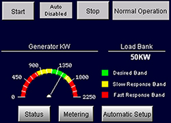
Automatic
Generator exercise, control from remote control contacts
Automatic exercise/test via programmable microprocessor control
Automatic load leveling/load regulation to maintain preset load on generator by sensing of total load and automatic addition or subtraction of load bank component.
Reverse power/regenerative power protection of generator by sensing power direction and magnitude and automatic addition of load bank component to act as a power sink.
Manual
- Generator exercise and testing via local or remote manual control
- Minimum loading of generators
- Malfunction Detection
Simplex Load Banks are equipped with a malfunction detection system which provides automatic load disconnect and alarm on sensing of an abnormal operating condition. The system includes:
Cooling air intake temperature switch, set at 120°F, to sense recirculation of load bank hot exhaust air or an ambient temperature above the rating of the load bank.